


- SAE/BOSS
| SAE/BOSS Thread Specifications | |||
|---|---|---|---|
| Thread Size | Nominal Size (in) |
Number of Threads per Inch | Male Thread O.D. (in) |
| 2 | 1/8 | 24 | 5/16 |
| 3 | 3/16 | 24 | 3/8 |
| 4 | 1/4 | 20 | 7/16 |
| 5 | 5/16 | 20 | 1/2 |
| 6 | 3/8 | 18 | 9/16 |
| 8 | 1/2 | 16 | 3/4 |
| 10 | 5/8 | 14 | 7/8 |
| 12 | 3/4 | 12 | 1-1/16 |
| 14 | 7/8 | 12 | 1-3/16 |
| 16 | 1 | 12 | 1-5/16 |
| 20 | 1-1/4 | 12 | 1-5/8 |
| 24 | 1-1/2 | 12 | 1-7/8 |
| 32 | 2 | 12 | 2-1/2 |
|
|
|
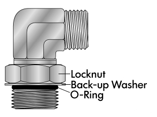
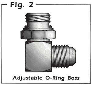
Fig. 3 Adjustable Port End Assembly 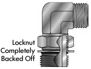
Step 4 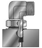
Step 5 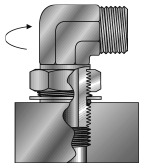
Step 6 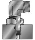
Step 7 & 8 |
- Inspect components to ensure that male and female port threads and sealing surfaces are free of burrs, nicks, and scratches, or any foreign material.
- If o-ring or seal is not pre-installed to fitting male port end, install proper size o-ring or seal, taking care not to damage it.
- Lubricate o-ring with light coating of system fluid or a compatible lubricant to help the o-ring slide past the port entrance corner and avoid damaging it.